|
|
Gear Planing is considered the most basic
process among the generating cutting processes of cylindrical gear
manufacturing. The cutting tool has a shape of a rack and as such the
process is suitable only for external gear manufacturing. The simulation
model can accurately predict the geometry of the undeformed chips as
well as the forces developed during the process. |
|
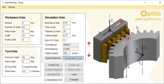
Input
Data |
|
|
Gear Planing process kinematics involve
three distinct movements: The rotary motion the workpiece, the
reciprocating motion of the cutting rack and the vertical movement of
the cutter along the workpiece tangent.
|
 |
|
3D Chips |
|
|
 |
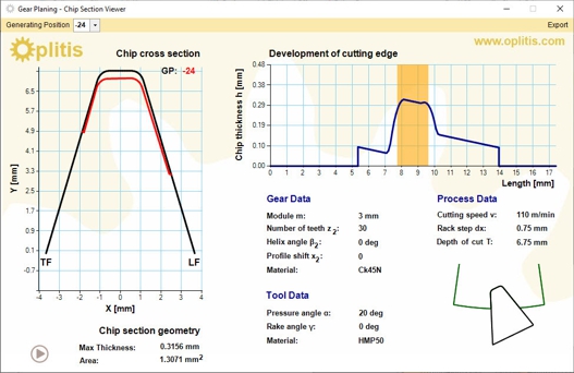
In gear planning the final gap is produced
by a series of successive generating positions (GP), which correspond to
different positions of the rack in relation the manufactured gear gap of
the rotating workpiece. The reciprocating motion of each generating
position removes material from the workpiece, forming a 3D chip which
can be calculated by the simulation model.
|
|
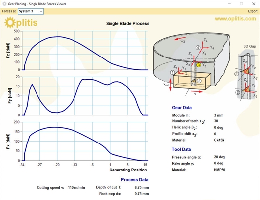
Cutting Forces |
|
|
Chip sections provide valuable information
that can be used in the prediction of the cutting forces. The
calculation is performed in four coordinate systems.
|
 |
|
3D
Gap |
|
|
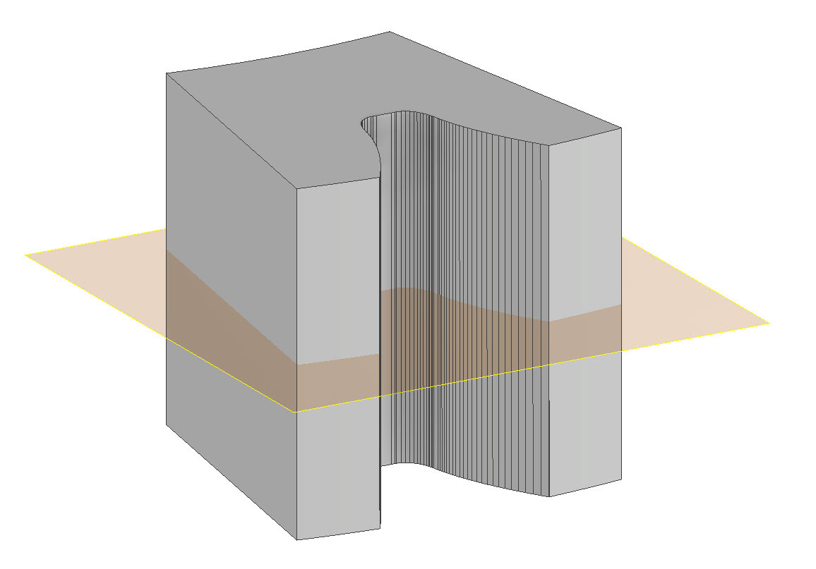
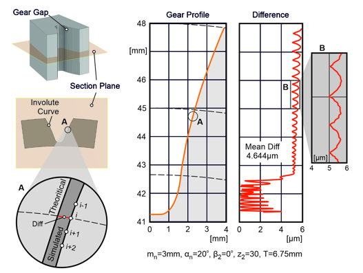
The 3D gear gap produced by gear planing is
verified by the comparison to theoretical involute curves.
 |
 |
| |
info@oplitis.com |